
Polarization-maintaining fiber cables


Polarization-maintaining singlemode fibers guide coupled radiation in two perpendicular principle states with different speeds of propagation, denoted the fast and slow fiber axes.
Linearly polarized radiation not coupled exactly into one of these axes is transformed into an elliptical state of polarization because of these different speeds of propagation.
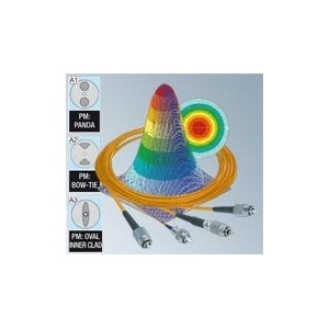
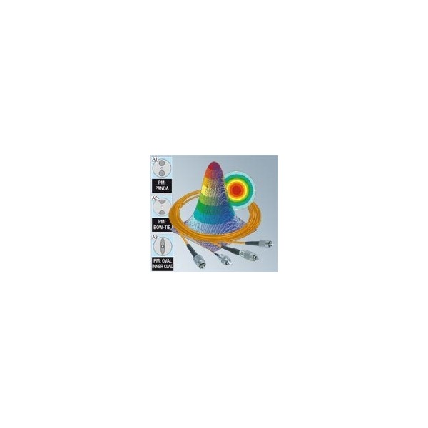
Polarization-maintaining fibers are either step-index fibers or photonic crystal fibers and the two unequal axes are caused by birefringence from stress-induction components in the fiber cladding, as in "PANDA" fibers, "Bow-Tie" fibers or "Oval-Inner Clad" fibers. The slow axis is orientated in parallel with the stress-inducing elements ("PANDA" and "Bow-Tie" fiber) or in parallel with the larger diameter of the inner cladding ("Oval-Inner Clad" fiber).
The linearly polarized laser radiation is usually coupled into the slow axis, because of its lower sensitivity to fiber bending.
The polarization-maintaining fiber cables made by Schäfter+Kirchhoff have the fiber axes aligned with the index key of the FC type fiber connector with extremely high precision (<1°).
The fiber cables made by Schäfter+Kirchhoff typically have a polarization extinction > 200:1 (23 dB) or > 400:1 (26 dB) for λ > 780 nm.
The three defining parameters of a polarization-maintaining singlemode fiber are numerical aperture NA, mode field diameter MFD and cut-off wavelength λco. Manufacturing tolerances of mean specified values may differ by up to 10%. Carefully selected fibers with characterized values are available on request.
| Curr. No. | Nominal wave- length λnom | Cutt-off wave length λco | Operational wavelength range [nm] | Mode field diameter MFD [µm] | Numerical Aperture NA [µm] | PM fiber type | Order Code |
|---|---|---|---|---|---|---|---|
| 1 | 360 Si | < 360 | 360–460 | 2.3–3 | 0.12 | P | PMC-360Si-… |
| 2 | 400 Si | < 400 | 400–500 | 2.8–3.5 | 0.11 | P | PMC-400Si-… |
| 3 | 400 Si | < 400 | 400–680 | 2.8–4.8 | 0.11 | P | PMC-400Si-… |
| 4 | 460 Si | < 460 | 460–550 | 3.2–3.9 | 0.11 | P | PMC-460Si-… |
| 5 | 460 Si | < 460 | 460–550 | 4.0–4.7 | 0.09 | P | PMC-460Si-… |
| 6 | 460 | < 460 | 460–630 | 3.2–4.4 | 0.11 | P | PMC-460-… |
| 7 | 530 | < 530 | 530–700 | 4.1–5.4 | 0.10 | P | PMC-530-… |
| 8 | 630 Si | < 630 | 630–780 | 4.4–5.5 | 0.11 | P | PMC-630Si-… |
| 9 | 630 | < 630 | 630–800 | 4.4–5.6 | 0.11 | P | PMC-630-… |
| 10 | 780 | < 780 | 780–1000 | 5.0–6.5 | 0.12 | P | PMC-780-… |
| 11 | 980 | < 980 | 980–1300 | 6.3–8.4 | 0.12 | P | PMC-980-… |
| 12 | 980 | < 980 | 980–1300 | 9.5–12.6 | 0.08 | P | PMC-980-… |
| 13 | 1300 | < 1300 | 1300–1600 | 9.2–11.3 | 0.11 | P | PMC-1300-… |
| 14 | 1550 | < 1550 | 1550–1800 | 10–11.6 | 0.12 | P | PMC-1550-… |
(representative selection)


