
Optical Fiber Ranger
Optical Fiber Ranger


Optical Fiber Ranger
Optical Fiber Ranger
1、General
JF-H360i is a portable testing instrument. The product is mainly used for measurement of the length of the fiber. It can also locate the faults and breaks of optical fiber. It’s widely applied in the manufacture, construction and maintenance in optical fiber communication system.
Main Features
l Portable, small size, light weight, easy for carrying
l Reliable performance, good repeatability
l One button operation, without complex setting, obvious results
l Easy to test the length and the break location of fiber
l Integrated visual fault locate system, convenient for testing fiber breaks in dead zone
l Silica gel key, provide comfortable operating handing feeling.
l 3AA1.5VAa alkaline battery, long operating time, easy to change, suitable for long time field operating.
l Suitable for the construction based on FTTX or access network and breaks location in maintenance
Main Functions:
l Testing fiber length, locate fiber breaks
l Test fiber distance of two nodes
l Test fiber repairment
2、Parameter
|
Type |
JF-H360i |
|
|
Fiber type |
SM |
|
|
Optical interface |
FC/PC |
|
|
Biggest display distance |
Reflection events |
60km(≥1.0dB) |
|
Non-reflection events |
20km(≥2.5dB) |
|
|
Dead zone in reflection events |
15m |
|
|
Distance accuracy(reflection events) |
±( 2m +2*10(-4)*distance |
|
|
Optical connector |
FC,SC,ST (PC) |
|
|
Operating temperature |
-10 ~+60 |
|
|
Storage temperature |
-20~+70 |
|
|
Power supply |
3AA 1.5V battery |
|
|
Outline dimension |
189*99.4*49.8 |
|
|
Weight(g) |
350 |
|
3、Accessories
1.JF-H360i optical fiber ranger-------------------------------------------------------1pcs
2.Operation instruction-------------------------------------------------------------------1pcs
3. AAA battery-----------------------------------------------------------------------------3pcs
4. FC/SC/ST conversion interface---------------------------------------------------1pcs
5. Clean cotton swabs-------------------------------------------------------------------1pcs
4、Function instruction
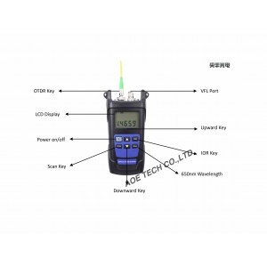
4.1 Button instruction:
Power supply button: when the instrument is power off., press this key, the machine will turn on. When the instrument is power on, press this button,you can choose automatic power off function, at the same time LCD display the upper left corner (10 min will auto power off ). pressing the button again to turn off the automatic power off function; Press the key (about 3s) to realize the power off function
SCAN: under the measurement mode, press this button and start the OTDR module to test the measured fiber and display the test values on the screen. Press down for about 5 seconds, entering the cycle test and display A at the top left corner. Under the automatic cycle test, pressing the button, the automatic cycle test will close.
Upward key: when you have multiple test values in measurement mode, click this button to view the previous value. Under the refractive index modification mode, press this key to modify the refractive index, adding 0.0001 per click.
Downward key: when you have multiple test values in measurement mode, click this button to view the next value. Under the refractive index modification mode, press this key to modify the refractive index, reducing 0.0001 per time.
IOR: in the measurement mode, press this button displays the current index of refraction, cooperate with the key to the refractive index changes, and then press this button to save the refractive index and return the test mode.
650nm: under the measurement mode, press this button to enter the visual fault locator test mode, and press this button to return the test mode.
4.2 Operation instruction:
Open the device and enter the main screen, as follows:
4.2.2 Clean tested optical fiber, access to OTDR interface. Pay attention to the tested optical fiber interface type, joint unmatched interface type of access equipment, it will damage the output end of the fiber, and get the wrong test results.
4.3.3 Press the SCAN button, the device begins scanning the optical fiber, which displays the SCAN progress. Instruments do not need to set the pulsed width, automatic adjustment in the process of scanning through powerful intelligent analysis software to calculate the optical fiber events within the scope of the entire test points. As shown in figure:
4.2.4 Test is complete, showing all the test values. The total event can display up to eight, scroll through the event values. The error of the reflection event is very small, and the error of the attenuation is greater. As shown in figure:
4.2.5 If the measurement value is in the blind area of the instrument or beyond the measuring range, it is shown as an empty event. As shown in figure:
4.2.6 In the fiber-optic repair work, the instrument is used to test the break position, and the maintenance personnel can use the automatic cycle test function, when they splice. Press the SCAN button for about 3 seconds until the SCAN display.
4.2.7 After measurement, show the value of the current break location.
5.2.8
4.2.8 The instrument automatically retests the interval for about 5s,and when the test value displays another value, it can be determined that the current breakpoint has been fixed.
4.2.9 Press the SCAN button to exit the automatic cycle test function.
4.2.10 Press the IOR button to enter the refraction modification page. As shown:
4.2.11 The refraction can be modified in the range of 1.0000 to 2.0000, the value is modified by the upper and lower keys, press the IOR key again, the refraction index is saved and quit the modification.
4.2.12 At the inquiry of high loss failure or breakpoint of short fiber or pigtail, you can use the function of visual fault location, need to exit automatic cycle test mode before the trial function Connect the fiber to the visual fault location port, press "650" button, as shown:
The red light can be seen at the ends or breaks of the fiber. Press again, the visual failure location mode is dropped.
Note: please do not look directly at the end of the fiber or the end of the fiber pigtail or the fault, in case the eye is damaged.
5、Common faults
|
Fault performance |
Possible reasons |
Resolution ways |
|
Device can't start |
Power supply don’t open |
Press the power button |
|
Battery is not enough |
Exchange battery |
|
|
The optical fiber refractive index setting is not correct. |
The index of refractive index of fiber optic fiber set up according to manufacturer’s requirement |
|
|
The test fiber length is inaccurate |
Optical fiber port is dirty |
Wipe the fiber optic ends with no anhydrous ethanol |
|
The connector is not matched |
Change matched optical patch cord,or need transmission line to transfer. |
If you still cannot solve the problem, please connect us immediately.
6、 Attentions:
1.Instrument internal contains laser and detection sensor, please do not illuminate directly in instrument sensors, or the sensor will disorder, even causes the damage of sensors.
2.Luminous key characteristics of the instrument will change with environment temperature do not make the instrument under direct sunlight.
3.Instrument light sources emit light pulses may cause harm to the eyes. Never look at the light at any time! In case of injury.
4.Before the "SCAN", the to be tested fiber must be connected to the port and then do operation. Do not remove fiber plug in the process of operation "SCAN", in case reflector effect damage the instrument.
七、Preserve and maintenance
1. Always keep the fiber test port clean, no grease, no pollution, do not use not clean and non-standard adapter connector, do not insert the polished surface of end face, otherwise it will damage the optical fiber test port, and affect the test result.
2. Use an adapter whenever possible.
3. Once the instrument is not in use, cover the dust cap, protect the face surface clean and prevent long-term exposure to dust in the air.
4. Be careful to plug in the adapter connector and avoid the scratches on the port.
5. Regularly clean optical fiber test ports. When cleaning optical fiber test ports, use a special cleaning cotton swabs to gently tap in a circular direction.
6.Remove the battery for long time no use, prevent the battery from being affected by moisture.
八、 Battery
In the process, if you find that the battery is low, close the test meter immediately, replace or recharge the battery.
九、 Quality guarantee
We do not approve of the user repairing the instrument.
1.The date of instrument warranty shall be within twelve months from the date of delivery. Our company will guarantee the material and workmanship of all its products, and the warranty will be valid for twelve months from the date of receipt. When the purchased product is found to have a quality problem during this period, our company will make appropriate repair or replacement. But in any case, our liability will not exceed the purchase price of the product.
2.If the instrument has problems in using process , according to the common failures suggest solution still cannot be solved, the user shall not open the case, please contact with the company's Marketing Department.
3.For the fault quality caused by manufacturing defect, the manufacturer is responsible for free repairing or replacing the instrument.The guarantee applies only to the normal use of instrument,with no damage and improper use.
4. The warranty of the company's hand-held series is not included in the following cause/failure:
1.Unauthorized repair or modification of the instrument;
2.Inappropriate use, neglect, or accident.
Note: the instruction of handheld light source, optical power meter, optical multi-meter, PON power meter, optical fiber ranger and penstyle visual fault locator is standard specifications, if you have updated version upgrade, without prior notice, the client if necessary, can download the update from the company website.


